FIELD TESTING OF ACOUSTICAL CLEANING
OF ELECTROSTATIC PRECIPITATORS
Lotte Buhl, Steen Drue* and Leif Lind
FLS miljo a/s, DenmarkAbstract:
Tests using a 20 Hz acoustic horn on a fly ash precipitator and two 125 Hz acoustic horns on a precipitator after a straw burning boiler are reported. It seems that the infrasound did not have the expected positive effect on the dust dislodgement. The higher frequency horns, however revealed an unexpected positive potential. The expectations and the experimental results are reported herein for use by others applying acoustic cleaning, for trying to confirm the results and for helping find the correct physical explanation of how the acoustic waves dislodge the dust, thus making it possible to optimize the system and the operation of acoustical cleaning.
1. Introduction
Dust precipitated on the collecting plate surface has to be removed, normally by vibrators or rappers. Often the cohesive forces in the layer are so large that proper cleaning is difficult to achieve, or the compressive forces, due to high resistivity, are so intense that vibration only works if the power is cut during rapping (power-off rapping). In some cases of moderately high resistivity it is probable that frequent vibration makes the surface particles move thereby extinguishing the contra emission in much the same way as a small fire is put out by throwing sand. Sometimes it is revealed that dust on the discharge electrodes causes increased voltage or decreasing current, apparently because the corona is suppressed due to the build-up of fine particles.
We have made a few sporadic attempts with acoustical cleaning in the past, mostly trying to solve an acute emission problem. The precipitators named below are hard at work but have not experienced any guarantee problems.
2. The acoustic horn
Papers describing the use of acoustic horns are often written by the horn supplier,
sometimes together with the precipitator owner, but hardly ever by the precipitator
supplier. Thus the virtues of an acoustic horn are usually described as follows: 'no need
for washing down the precipitator', 'no hopper build-up problems' or 'less reentrainment',
the latter normally considered a paradox, since the field is 'tooted' as a whole in
contrast to partial vibration or rapping.
The most common type of horn works with frequencies between 125 to 250 Hz. The
horns have a reasonable size for installation on a precipitator and are reasonably priced.
Less commonly used however, are low frequence horns, or infrasound horns, with frequencies
of 15 to 20 HZ. The term 'infra', meaning sound with frequencies below the hearing limit
of the human ear, must be received with a grain of salt, as the sound contains a lot of
high intensity overtones. Different types of horns are described in papers and brochures,
see references [1]-[4].
Some types use a diaphragm, vibrated mechanically or pneumatically. Others, especially infrahorns, use a regular siren. In the latter case, a control system is needed to keep the frequency fixed at resonance.
3. Physics
3.1 Dislodgment mechanisms
The physics of the influence of sound waves on the dust layer is not well understood. In fact only some presumptions about the possible mechanisms of the dust dislodgement exist which is the case with dust dislodgement from vibrating or rapping.
Acoustic horns long have been used for purifying boiler or heat exchanger tubes of soot or dust, especially in areas where the fuel has been peat, wooden chips or bark. Normally acoustic soot blowing is continually applied, which is believed to be detrimental to precipitators due to the redispersion of the dust.
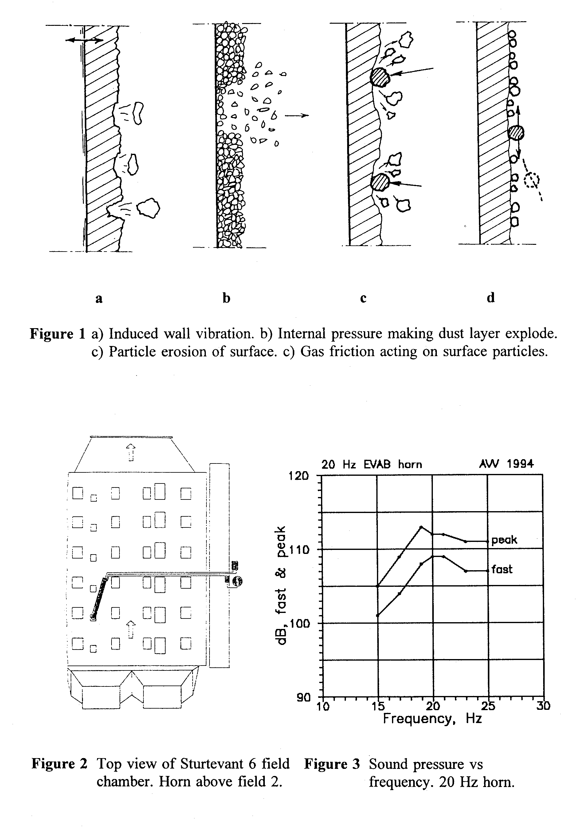
K.E. Widell [5], when describing possible physical mechanisms of the sound waves in 1982, hypothesized that induced vibration of the heater tubes might be one explanation. This is, however not plausible, he found, since 20 Hz and a 5 mm gas displacement amplitude corresponds to only 2 g* (1 g* being the acceleration of gravity), as compared to 10 000 - 1 million g* necessary to loosen the fine particles. See figure la.
Widell felt another explanation might be the sound pressure fluctuations influencing the dust cake directly. He theorized that a porous dust layer acting as a Helmholz resonator might create high internal gas pressures. Using this theory (which has not been confirmed) it is still difficult, however, to explain pressure forces high enough to break up the dust layer. See figure lb.
Widell's third theory claims that the acoustical movements of the gas make the particles wear away the surface layer. See figure ic.
Finally, according to Widell, the most plausible explanation might be that the gas movement influences the particles, due to friction, at the surface and thus removes them. In continuos soot blowing, this mechanism might be interpreted such that the particles never have the opportunity of settling on the surface. In case of a precipitator, where the horn is only activated for seconds to tens of seconds and then cut off for several minutes, the sound cannot prevent the dust from settling. As an example, Widell takes a sound pressure of 134 dB re. 20 ÁPa and a frequency of 20 Hz and finds an RMS pressure of 100 Pa and an RMS velocity of 0.3 m/s. The corresponding displacement amplitude is 5 mm, and the momentum is believed to be high enough to clean the surface. See figure 1 d.
3.2 Sound propagation
While a boiler has an extended free space, a precipitator is filled up with internals shadowing and absorbing the sound energy. In an empty space, the sound waves can cover a cube with edge measures according to the wavelength (range one wavelength). For smoke gases at 120 C, the wavelengths at frequencies of 20, 125, 250 and 500 Hz are approx. 20, 3.2, 1.6 and 0.8 m respectively. The lower the frequency the less the internals distort and attenuate the sound intensity. Tony Chebib [6] demonstrates that sound in ducts propagate as plane waves (intensity independent of distance from source) if the transverse measurement of the duct is less than the speed of sound divided by 2 times the frequency. For a 20 Hz wave this corresponds to 9.5 m and for 125 Hz to 1.5 m at 120 C. The wall absorption is proportional to the square root of the frequency. As gas attenuation is presumed to be much less than wall absorption, the attenuation ratio between 125 and 20 Hz waves is about 2.5.
Some claim low frequency waves are responsible for ruptures in the internal parts. Theoretically this is possible, but limited on-times, ranging from seconds to tens of seconds, should prevent internals from developing resonance oscillations.
4. Laboratory examinations
The direct influence of an acoustical wave on a dust layer was examined in the laboratory with and without an electrical field. Video recordings did not reveal any movement visible to the eye, electric field or not, in a sound field of 129 dB re. 20 Pa using a thick steel plate as a base. Yet, surface movements were clearly seen if the dust sample was contained in a less rigid Petri dish.
Out-of-plane peak accelerations of a 1.5 mm plate 1.5 m from the horn exit were recorded. The 20 Hz horn gave 6.5 g* and the 125 Hz horn 2.8 g*, the latter giving only 102 dB re. 20 ÁPa due to a badly shaped bell.
5. Field testing
Two different installations were chosen for field testing. A single 20 Hz horn on a 6 field precipitator chamber after a coal fired boiler in Asnaes, Denmark, and two 125 Hz horns on a 3 field precipitator for a straw-fired boiler in Rudkobing, Denmark.
The testing was not performed with permanent operating horns, demonstrating their potential over a very long period of time. Therefore, it was necessary to establish criterions for the effect of the horns. The practical possibilities included logging field current, voltage and spark rate plus extinction in rapper and horn mode together with the VI recordings. All measures are more or less integral criterions since detailed estimation of the possible dislodging mechanisms cannot be made.
If a main part of the dust layer breaks off due to the sound waves, a drop in the voltage for a given current density would be expected. If the discharge electrodes are cleaned by the waves however, the same change would be experienced, thus making differentiation between the mechanisms difficult.
The cloud of particles coming from dislodged and redispersed dust creates a space charge causing an increased spark rate. The dislodging efficiency can hardly be judged from the change in spark rate however, because dust coming off as lumps will
not necessarily cause sparking. The very first toots will dislodge dust from other internals than the electrodes, causing very high emission peaks only to disappear after a few toots.
These coinciding phenomena make it difficult to determine whether rapping or tooting is most effective for a given precipitator.
5.1 20 Hz horn
Such horns are rather expensive, more than $40 000 per horn including a 1 m3 pressure vessel, and the compressed air consumption is relatively high. Advantages are the high sound energy, the high gas displacement amplitudes and the range of the infrawaves.
A single EVAB F-II horn was installed on a roof inspection door above field 2, see figure 2. The horn is supplied with a rotating slot siren driven by a 3 phase electromotor, the rpm of which is controlled by a frequency converter. The control is looking for resonance of the siren base plate using an accelerometer and a feed back system. The resonance tube, corresponding to approx. 1/4 wavelength, is a bit longer than 4 m.
The Sturtevant precipitator has a field width of 12.32 m, a height of 14.0 m and a length of 1.98 m. Duct width is only 0.220 m. Rappers hit the plate leading edges at two levels. In the clean gas duct, a SICK RM-4 1 opacity meter was installed.
Sound pressure versus frequency was measured in the electrode spacing by lowering a microphone down from the roof, see figure 3. The peak value is 113 dB re. 20 ÁPa compared to 120-130 dB, found in the laboratory, giving a peak sound pressure of 8 Pa instead of 20-60 Pa.
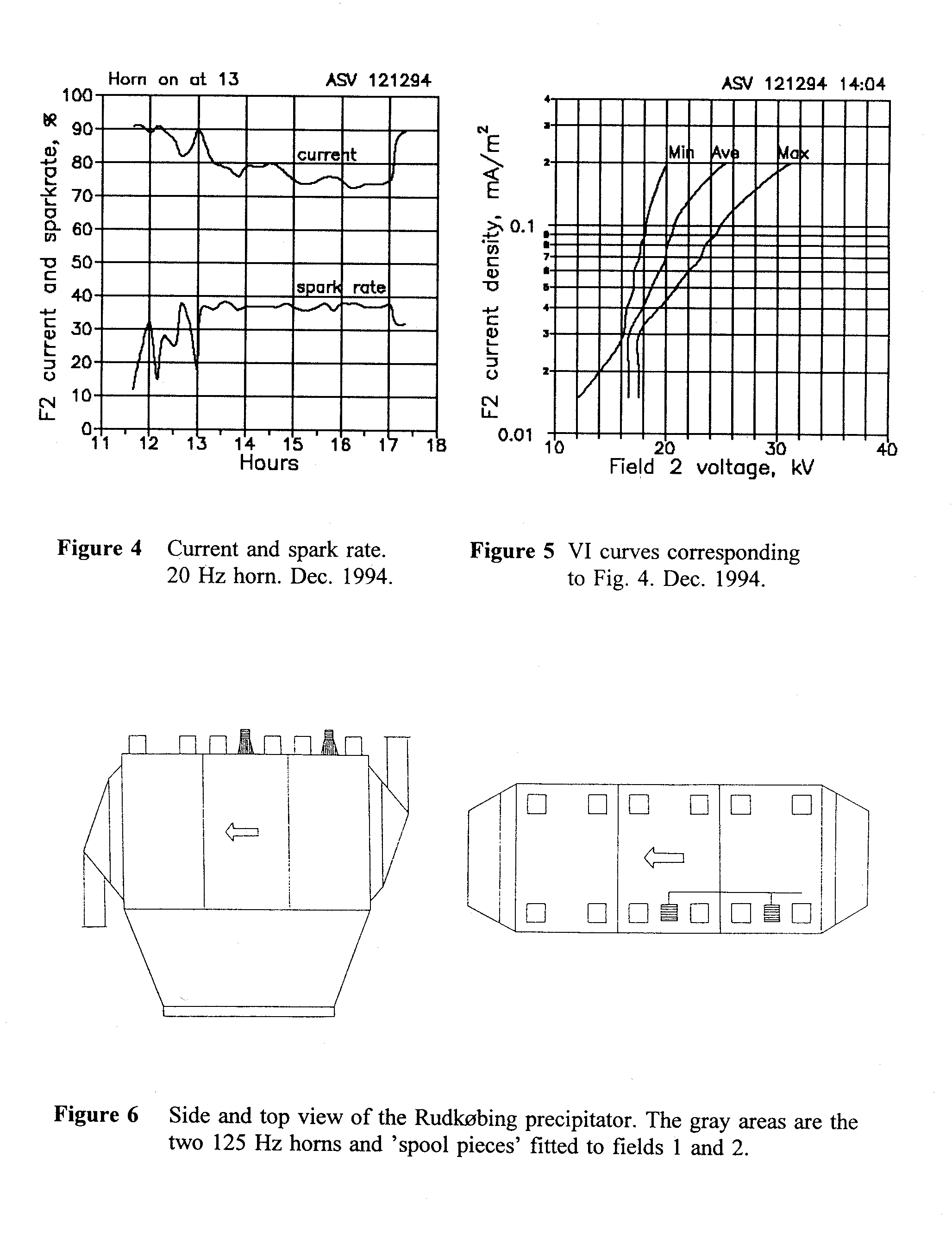
In figure 4, current and spark rates with a shift from rapper mode to horn mode around 1 o'clock are detailed. (The two layers of rappers were not stopped simultaneously). Rappers-alone gave a current 90-100% of the current limit, horn-alone 6nly 75%, while spark rate increased from 20% to almost 40%. Rapper timers were set at 60 seconds on (1 revolution) and 3 minutes off, and horn-on and horn-off were set at 12 seconds and 3 minutes. The corresponding VI curves in figure 5 reveal moderate resistivity. Trough-voltage is marked Mm. and peak-voltage Max. No peaks were visible on the opacity meter, rapper mode or horn mode.
It was concluded that the horn does not do the work as well as do the rappers due to inadequate cleaning of the plates.
5.2 125 hz horn
ENVIROCARE high frequency horns are somewhat cheaper, $5,000 per horn installed, and the compressed air consumption is considerably less. They operate with an oscillating diaphragm and a 750 mm bell. The supplier states 140 dB re. 20 ÁPa at the bell exit. The bell tube was fitted to a pyramidical box ('spool piece') welded onto the internal roof of field 1 and 2 by the roof side, due to insulator compartments, rectifiers and cable ducts. The horns point directly towards the angle irons supporting the collecting plates . The last field was not supplied with a horn. Precipitator sketches are seen in figure 6.
The boiler delivers heat to the district heating and steam to a turbine driving an electric generator. Straw from the surrounding fields is the fuel source. The dust is fine, mixed with a fog of aerosols, and resistivity and the content of aerosols depend on the particular grain type and on the type and amount of fertilizer used. Grain types are barley, rye and wheat, the latter being used for the operation dealt with here. Apart from high resistivity dust, treated in a precipitator with low current density, the gases contain unburned particles, which ideally need high current density in order to make the particles stick to the plates.
Sampling was performed using a PIACS EXPERT system, making it possible to bring home data as hard copies and floppy diskettes.
Collecting rapper timers were set at 80 seconds on (1 revolution) and 2, 3 and 5 minutes off for the first, second and third field respectively. Discharge electrode rapping on-time was 90 seconds (1 revolution) and off-time was 2 minutes. On-times for the horns were from 12 to 25 seconds, while off-times were varied from 12 to 60 minutes.
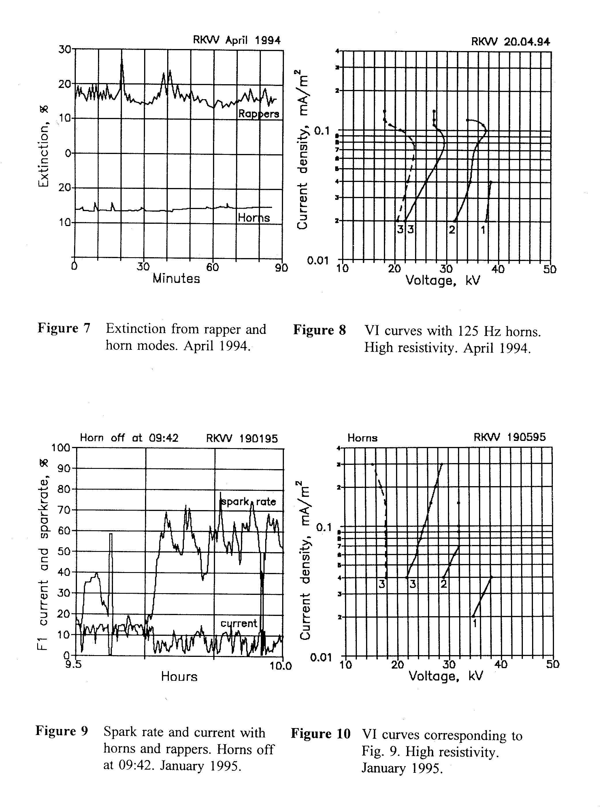
A comparison between opacity meter signals from rapper and horn operation is shown in figure 7. It is worth noting that the 'rapping' peaks are less with horns. The emission level seems smaller, but one must be cautious, because the straw gives a rather uneven gas and dust composition, which changes all the time. The VI curves from the horn mode is seen in figure 8. The courses indicate high resistivity dust on the plates, judged from the steepness of the trough (Mm.) voltage of field 3, in figure 8 shown as a dotted line.
Figure 9 shows, how spark rate goes up and current goes down after shifting from a horn to a rapper mode. The emission was hardly influenced. The VI curves of figure 10 reveal a high resistive operation.
Over a period of 24 hours the discharge rappers of field 1 and 2 were stopped, and observations demonstrated that there was no influence on current, spark rate, voltage or emission.
The noise on the roof, 1 metre from the horns, was measured. Almost 89 dBA, averaged over 30 seconds, and almost 99 dBA peak, both re. 20 Pa. However, trapping the noise is relatively easy and cheap since the sound has a constant frequency.
6. Some comments on the use of acoustic horns
The high emission peaks seen with the very first few toots indicate that dust is dislodged from other internal parts than collecting plates and discharge electrodes, namely ceiling, walls and hoppers. These first peaks almost stalled the examinations of the Rudkobing straw burning plant, since they were taken as an indication of the 'severe reentrainment from acoustic horns'. This is incorrect. After 2 - 3 toots, the peaks were below those of the rappers. On the contrary it demonstrated that the horn can keep other important internals, including inlet and outlet screens, clean.
If rapping systems can be replaced by acoustic horns on some precipitators and on some processes, initial expenditure and maintenance costs can be reduced. Rapper wear and fatigue life problems disappear. But it is crucial that the horn suppliers become more aware of the problems with diaphragm corrosion, diaphragm fatigue
ruptures, smudging from compressed air etc., even though maintenance is easy, largely because the horns are external to the precipitator, and the spare parts are relatively cheap.
Field testing showed that a single infrasound horn could not compete with the rappers. Yet, it is believed that optimization of a precipitator unit fully equipped with horns, might achieve a low frequency acoustic vibration which can do the job.
Field testing using high frequency horns demonstrated that it was possible to replace the rappers with 125 Hz acoustic horns, which did the work just as well, if not even better.
The reported examinations are not claimed to be fully explored nor to be typical for all precipitators. Starting out very doubtful, we skeptics now have a more balanced attitude. It is hoped that others will dare supplying precipitators with acoustic horns in the future and collect more knowledge about the acoustical potential to the benefit of precipitator users and suppliers alike.
Apart from additional field experience, clarification of the underlying physical mechanisms for the dust dislodgement is needed in order to reach the optimal solution.
8. References
[1] 'Clyde F-II Sound Generator'. Brochure from Clyde, Scotland, 1984.
[2] EnviroCare Industries Inc. 'Acoustic Horn' Brochure, CA, USA.
[3] Shelton, J.L and Hayes, T.L.
'Acoustic Cleaning Applications in Electrostatic
Precipitators'
10th Particulate Control Symposium & 5th ICESP,
Washington, 1993.
[4] Andersch, Torsten & Kramer, Paul
'The use of acoustic horns within a cement plant'. World cement,
Jan.1995.
[5] Widell, K.E.
'Low frequency Sonic Cleaning. A Review of possible
Mechanisms'
INFRASONIK, 1982.
[6] Chebib, T.
'Etude sur la propagation des ondes infrasonores dans une
conduite' Universite Paul Sabatier de Toulouse, 1981.
* Presently with MAGNEMAG, Denmark


